Phasor Diagram Of A Purely Capacitive Load Circuit What Is T
Inductive reactance and capacitive reactance Purely resistive, purely inductive and purely capacitive circuits for jee Purely capacitive circuit phasor diagram
14+ Phasor Diagram Of Rlc Circuit | Robhosking Diagram
What is a power triangle? active, reactive & apparent power Phasor diagram of inductor in ac circuit Purely inductive ac circuit| expression of current & power, waveform
What is a purely inductive circuit? circuit diagram, phasor diagram
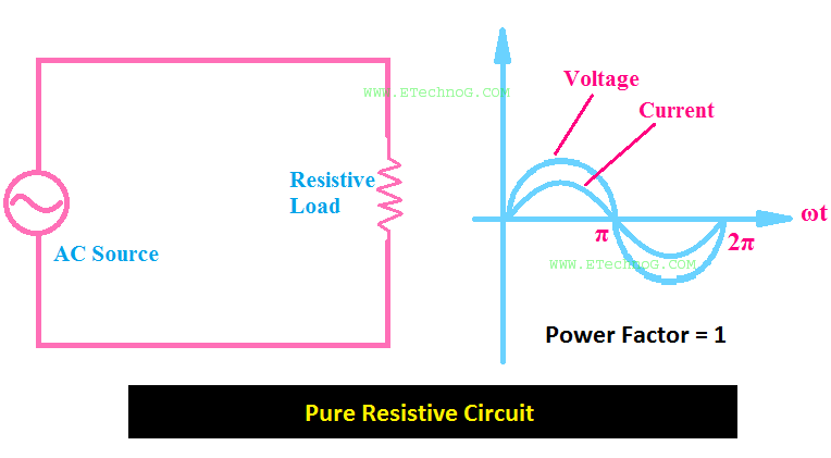
Purely capacitive circuit phasor diagramWhat is capacitive circuit? formula & function Reactance inductive capacitive circuit phasor inductor phasePower factor of alternating circuit containing pure resistor.
Capacitive phasor diagramPhasor representation of one phase ac circuit presentation Purely resistive circuitPhasor diagram of transformer on lagging load.

Inductor lagging current
Draw the timeWhat is power factor? Power circuit factor unity pure resistive alternating resistor current ac advantages containing both voltage phase same alsoCircuit purely phasor capacitive diagram animated resistive rlc applet adding phasors gif interactive example.
Circuit capacitive inductive cosCapacitive phasor Ac capacitance inductance phasor diagram circuit inductive capacitive reactance analysis gif physics emoPhasor diagram of capacitor.

Ac capacitance and capacitive reactance in ac circuit
Purely capacitive circuit phasor diagramCapacitors lagging impedance inductor inductors phasor inductive ohms circuit ohm expand generalize 14+ phasor diagram of rlc circuitWhy power in pure inductive and pure capacitive circuit is zero?.
The phasor diagram in case of capacitive load supplied by power qualityPhasor diagram of capacitive load Understanding the phasor diagram for a capacitive circuit: a visual guideWhat is power factor?.

Ac circuit containing only a capacitor
[diagram] purely capacitive circuit phasor diagramCapacitor phasor diagram What is a purely inductive circuit? circuit diagram, phasor diagramWhat is the symbol for inductive reactance at graham odell blog.
[answered] the phasor diagram shown below represents cot purelyCapacitive purely phasor For a purely inductive ac circuit show that the current lags theDiagram transformer load phasor capacitive vector condition draw circuit vectorified.
Transformer on load condition
.
.


